What should you pay attention to when designing an anechoic chamber?
(1) The requirements for the interface sound absorption coefficient are quite different between the test items of pure tone signals and the test items of broadband noise signals.
When the interface sound absorption coefficient a=0.99, that is, |R|=0.1, the range of deviation △L=1dB is r<0.2L, and the range of △L=-1dB is r<0.18L. Most of the testing of loudspeaker electroacoustic parameters uses pure tone signals. Therefore, the interface sound absorption coefficient is generally required to be greater than 0.99 to meet the requirement of sound field deviation less than ±10% at a large enough testing distance. If △Ln<1dB is required, even if r=L/2, that is, the measuring point is close to the interface, only a=0.88 is enough. Especially when measuring the machine radiated noise power level in a semi-anechoic chamber, the free sound field deviation is allowed to be ≤±2 dB or ±3 dB, so the interface sound absorption coefficient does not need to reach 0.99.
(2) What follows is the design of sound-absorbing structures.
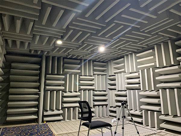
For sound-absorbing structures that require a sound absorption coefficient ≥ 0.99, a wedge shape is generally used. Because the sound absorption mechanism of porous materials is that there are a large number of air gaps connected by air flow inside the material, forming thin tubes or even capillary tubes. When sound waves are transmitted to people, the vibration of the sound waves in the thin tubes is converted into heat energy due to internal friction and is absorbed. The sound absorption capacity is related to the void ratio of the material (for example, the void ratio of glass wool is about 96%), flow resistance and the fiber structure of the material. At the same time, the frequency characteristics of sound absorption are related to the thickness of the material, that is, the lower limit frequency of the maximum sound absorption is approximately the frequency of 1/4 wavelength corresponding to its thickness. To achieve good low-frequency sound absorption, the thickness of the porous sound-absorbing material must be increased. However, due to the flow resistance of the material, the thickness cannot be increased arbitrarily to extend low-frequency absorption. Various porous materials have their effective thicknesses.
Therefore, in order to extend the high sound absorption characteristics to low frequencies, the porous material is made into a wedge shape. Judging from the cross-section of the wedge structure, it gradually transitions from the air medium to the porous material, and the acoustic impedance has a gradual change process, so that the sound waves can be transmitted deep into the wedge structure and be converted into heat energy and consumed.
Of course, it is necessary to design a sound absorption coefficient above 0.99. In addition to the parameters of the material itself, it is also related to the shape of the wedge (the angle of the wedge and the ratio of the wedge to the tip). The total length of the wedge determines the lowest frequency with the maximum sound absorption coefficient (generally called the lowest frequency with a sound absorption coefficient greater than 0.99 as the cutoff frequency of the wedge). Approximately the total length of the wedge corresponds to a frequency of 1/4 wavelength. If the resonant sound-absorbing structure between the base of the wedge and the depth of the cavity behind the wedge is used, the cut-off frequency can also be slightly extended to low frequency.
In the case of testing broadband noise signals, especially the measurement of the sound power level of noise sources in semi-anechoic chambers, in many cases it is not necessary to adopt the design of a sharp sound-absorbing structure. For example, when designing a semi-anechoic chamber for measuring the sound power of large motors for an enterprise, a multi-resonance sound-absorbing structure with three layers of cloth was used to test fire-proof cloth of different materials in a low-frequency standing wave tube, changing the relationship with the rigid wall. With a minimum placement distance, the sound absorption coefficient above 100Hz is greater than 0.86, completing the design task of a semi-anechoic chamber in a very economical manner.
(3) Considerations about the size and shape of the anechoic chamber.
Generally, the architectural shape of an anechoic chamber rarely uses the shape of sphere, columnar or arc surface. Because if the sound absorption coefficient of the sound-absorbing structure is completely greater than 0.99, the impact of the shell shape is not significant; but when the sound absorption coefficient is very lower than 0.99, at least below the cut-off frequency of the sound-absorbing structure, the sound absorption coefficient drops sharply. A large concave surface will produce a focused sound defect, making it completely impossible to obtain an approximate free sound field.
For the test of machine radiated noise power, the measuring points are generally arranged in the space around the equipment, so it is mostly designed as a square or rectangular semi-anechoic chamber. Its length, width and height can be estimated, that is, according to the requirements of the relevant test standards The measurement distance, measurement position, and allowable deviation from the free sound field are used to determine the size of the side length and height. Of course, appropriate allowances will be made, and the size of the equipment that may be available in the future must also be considered.
For parameter measurement of electroacoustic devices, if the sound source (speaker) is placed in the center of the anechoic chamber, the microphone is placed along the axial or diagonal direction of the plane (generally the test distance is 1m, for large-size speakers and line arrays and other speaker systems , requiring a larger test distance), the size of the anechoic chamber will be larger. The general consideration is to set the center of the sound source and microphone test line at the center of the anechoic chamber, and the test line is along the diagonal direction of the plane. The shape of the anechoic chamber is rectangular. This arrangement saves the space of the anechoic chamber. When the free sound field is evaluated after completion, the sound removal source is placed in the center of the anechoic chamber for measurement. In this case, the range of the free sound field within a certain deviation (±ldB, ±2dB, etc.) is obtained. In addition, the test sound source is placed in the future. Place the speaker under test. Detect the distance from the test (diagonal direction of the plane) and the deviation from the ideal free sound field.